
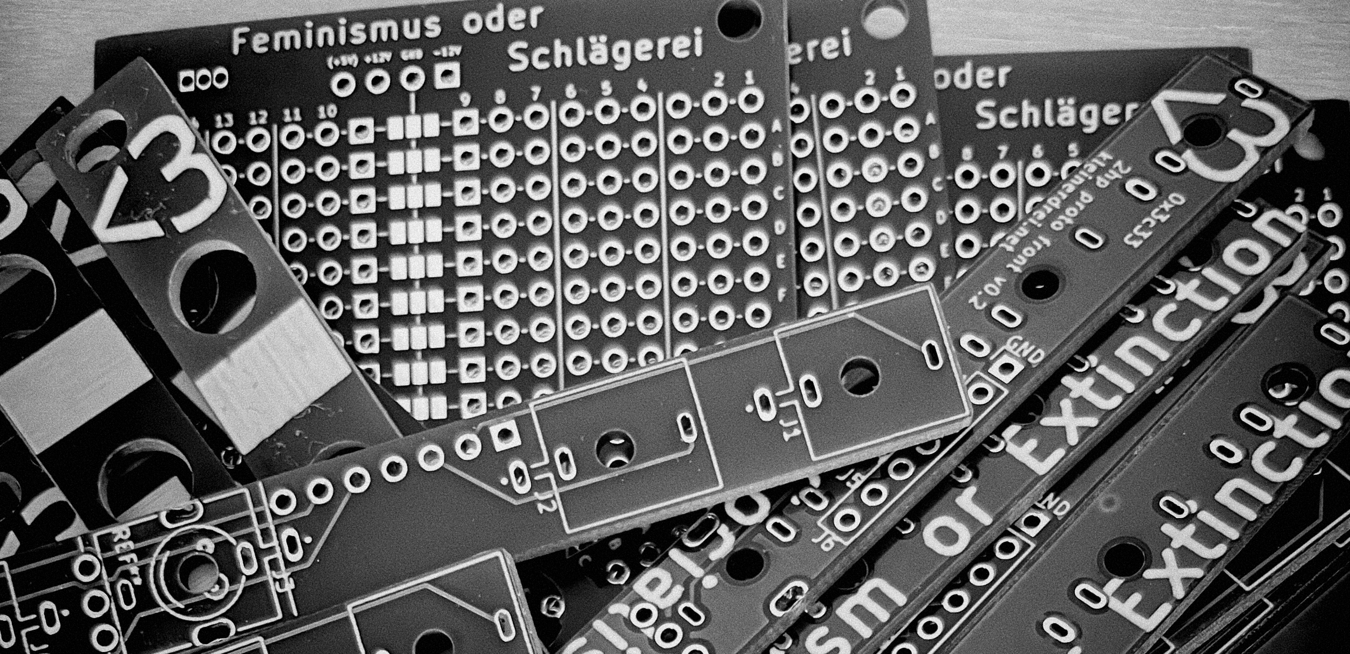
I like to build simple modules for my eurorack synthesizer myself. There is some stuff that is always the same. Mostly power related. Or the part where you need some sockets to plug your patch cables in. I’m just too lazy to start it every time from scratch again. So, after a bit of experimenting and building generic PCBs for the sockets part, I found out about the P-0+o prototyping board from Kristian Blåsol.
It is a really nice board to build little modules with. It has a dedicated place to put your power connector and three busses in the middle of the board for distribution.
I took this very good idea and designed a board fitting my personal needs. The P-0+o board seems to be more about real prototyping and tinkering around developing an idea. But I needed something to build a module I’d actually use. My “nucleus” board lacks of a few features of P-0+o, but adds some others.
I gave some of those boards to my friends. And because it can be a bit complicated, I promised to write some kind of a how-to – through whose introduction
you just made it. Congrats. Now to the interesting stuff.
How to use nucleus
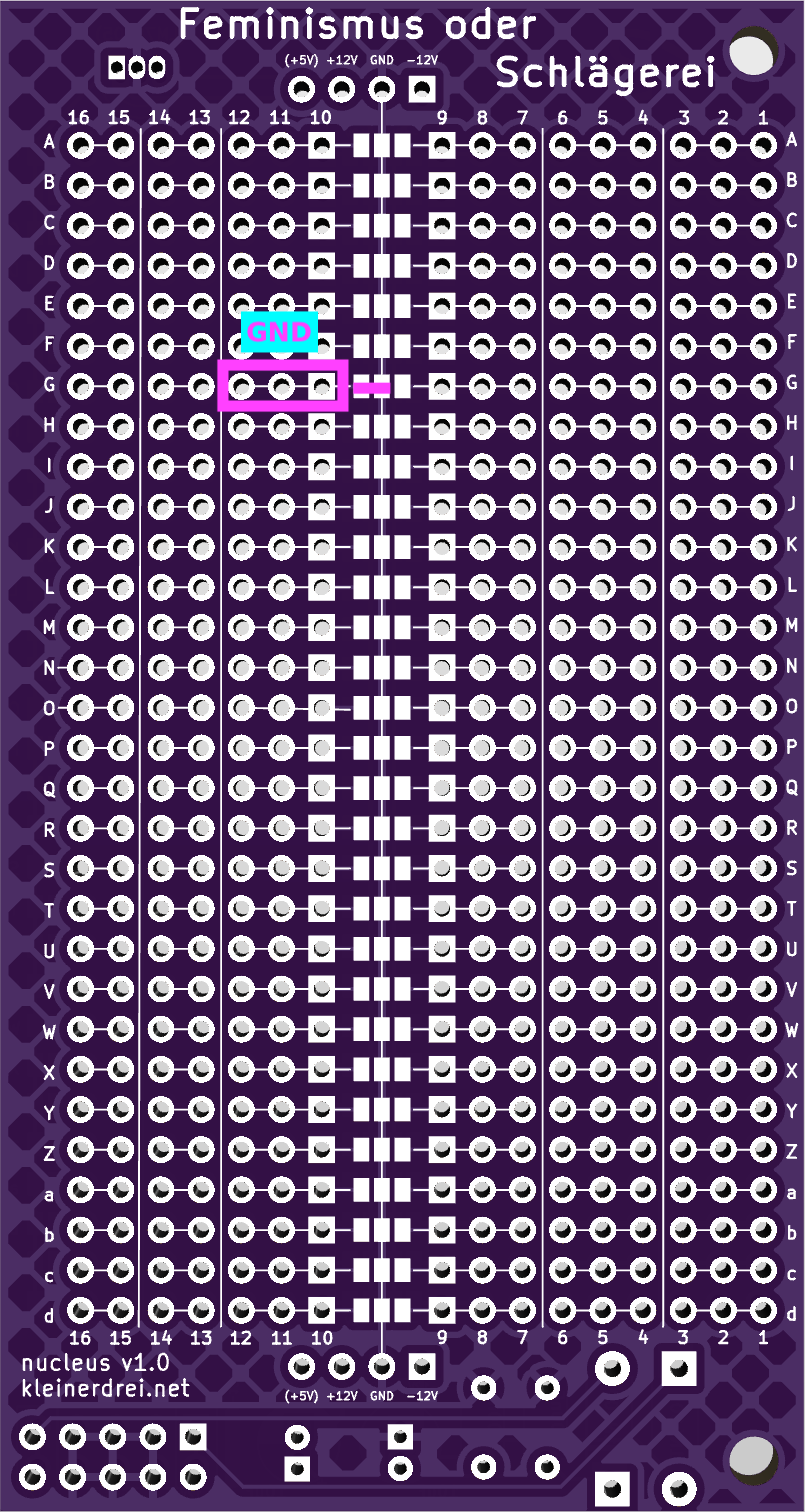
nucleus ist mostly used like a normal TriPad board. Components are placed on the board, connecting different horizontal sections of two or three holes. Interconnected holes and pads on the grid are indicated by a thin connecting line printed on the PCB. Breaks between sections are indicated by vertical lines between holes.
Power input
In the lower right corner is a spot to place a 2x5 pin header for standard eurorack power supply. To its left, it is possible to place capacitors and diodes. The diodes are meant to protect the module from reverse polarity, in case of a connector being plugged in the wrong way round. The capacitors are supposed to smoothen possible peaks to reduce noise.
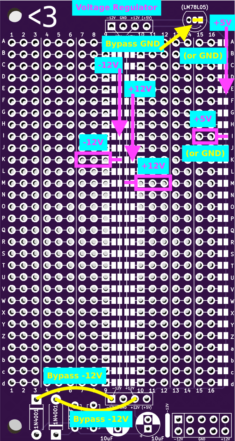
For a quick draft, when this is not needed, it is possible to just bypass the “power cleanup” section with two pieces of wire from the lower holes of the 10μF capacitors to the connectors below the grid (see graphic “nucleus front”).
In the upper right corner a voltage regulator (my recommendation would be a LM78L05) can be placed to have +5V available for a microcontroller or something like this.
Power distribution
To distribute power over the board, there are four busses. On the front side we have two in the middle, the left one delivers -12V and the right one +12V. On the right edge of the board is a third bus. It delivers +5V from the voltage regulator. In the middle of the back of the board is only one bus for GND.
It is also possible to connect for instance the right two contacts where the voltage regulator should be placed (see graphic “nucleus front”) to get a GND bus instead of +5V.
To connect the adjacent section of holes to a bus join the two solder pads with a drop of solder (see graphics).
-
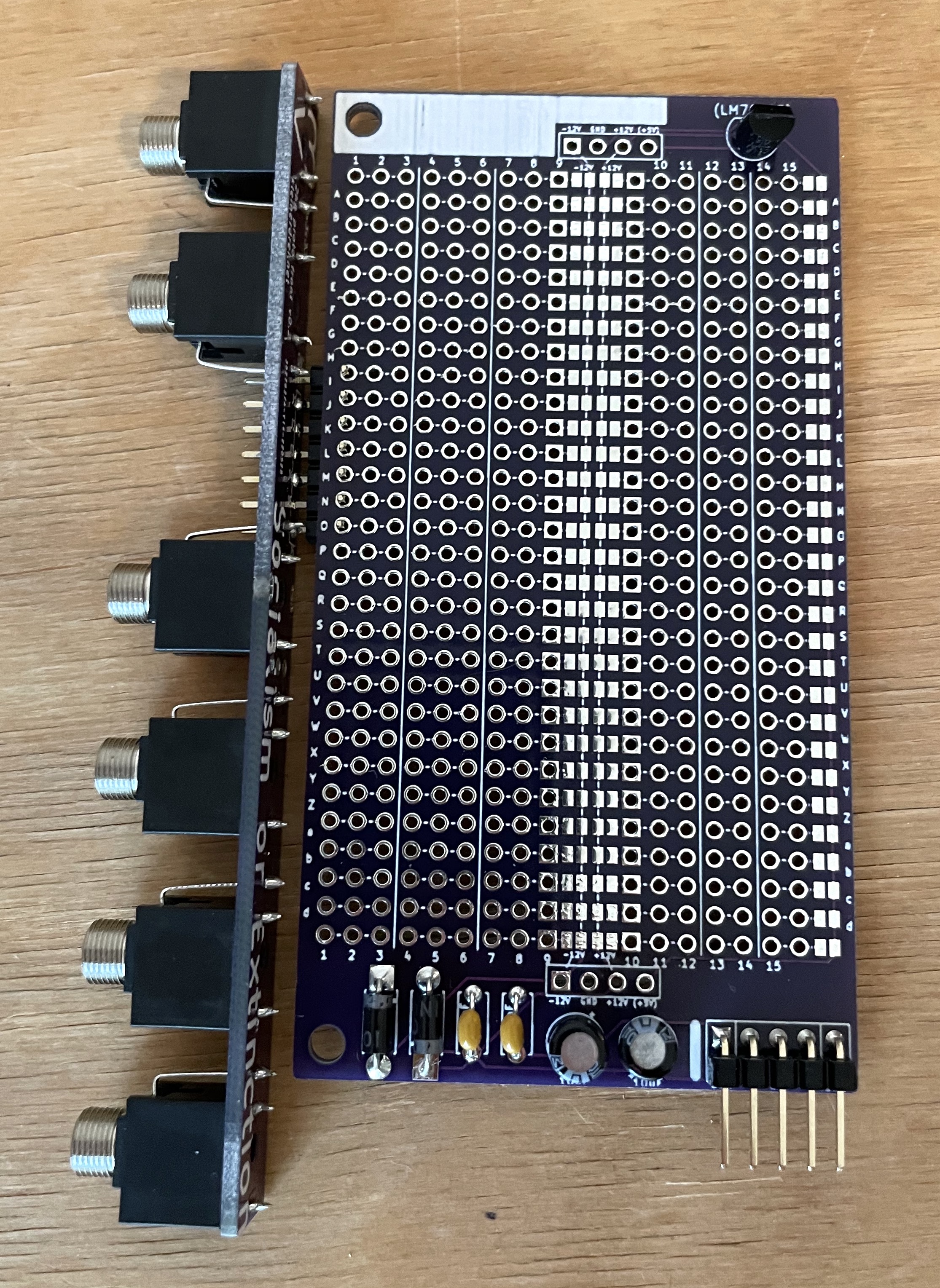
Yes correct, the board with the sockets is not soldered to the nucleus board. I just wanted to show how it could be used.
-
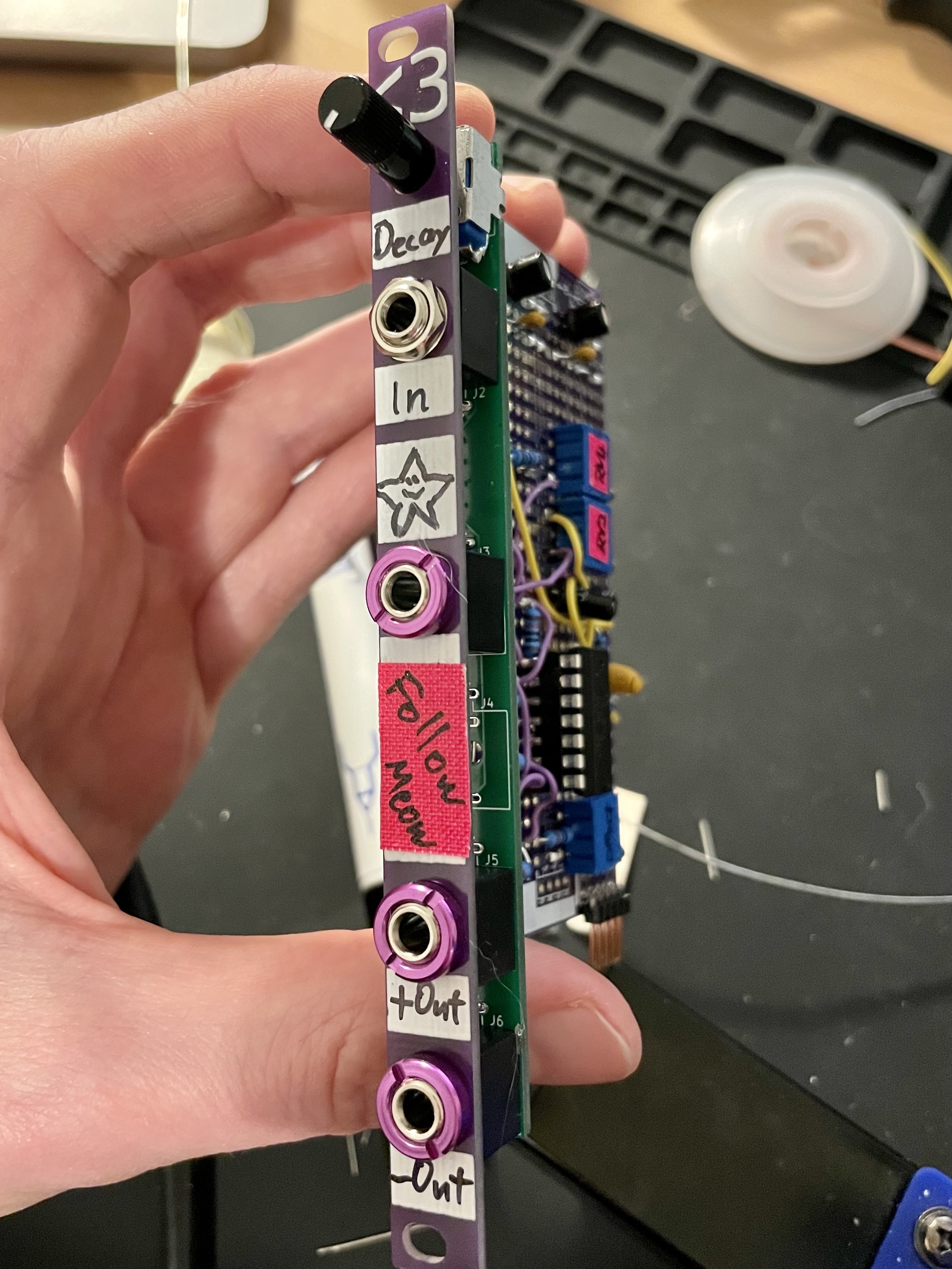
Follow Meow - an envelope follower, built using nucleus (older version)
Contact me, if you want some nucleus boards.