The Intellijel Metropolix is my main and favourite sequencer for a lot of reasons. But one limitation I always bump into with this thing is that it has far too few outputs for all the stuff it can do on the inside. It is possible to extend it with the Gx/Qx, but those only can do on/off signals (triggers or gates), no graded control voltages (CV).
In August 22 I posted a request at the Intellijel forum to get a Metropolix CV expander. A fairly long time after that, I started to feel a bit dumb about it, because there was a firmware Update for the Metropolix in February 22, which added MIDI over the USB port on the modules back. So why not just connect this to one of the many MIDI-to-CV modules?
With a MIDI 1U for instance, one would get secondary outputs for one track, plus clock (dividable/multipliable), plus CV for velocity, and two CV or Mod lanes. Extended with a CVx, the MIDI 1U could provide additional separate outputs for all 8 Mod lanes.
Because the Metropolix as well as the MIDI 1U are USB devices and are not able to act as an USB host, they cannot be connected directly. There are a lot of solutions for this problem out there, DIY or from the shelf. Most of them are too big or expensive or both. I wanted a connection that would be small enough to stay in my case and had no cables or something out of it.
One of the few advantages of capitalism is the fact that microcontroller boards are cheap these days. So, I built my “connector” with a little Adafruit Trinket M0. Those are hard to get at the moment, but it should be easy to do the same trick with an ESP32 or mostly any SAMD21 board like the Adafruit Feathers (I don’t get paid by them, really!).
The idea is to have the microcontroller board (here “Trinket”) act as an USB host for the Metropolix to connect to. The Metropolix sends the MIDI information via USB to the Trinket which “unpacks” the MIDI and just sends it out as good old serial MIDI.
To connect the Metropolix and the Trinket, an USB OTG cable or adaptor is needed. Those can be bought or easily DIYed.
Hardware build
(As always: If you try this yourself, it’s your own risk. Don’t blame me for damaging your precious gear!)
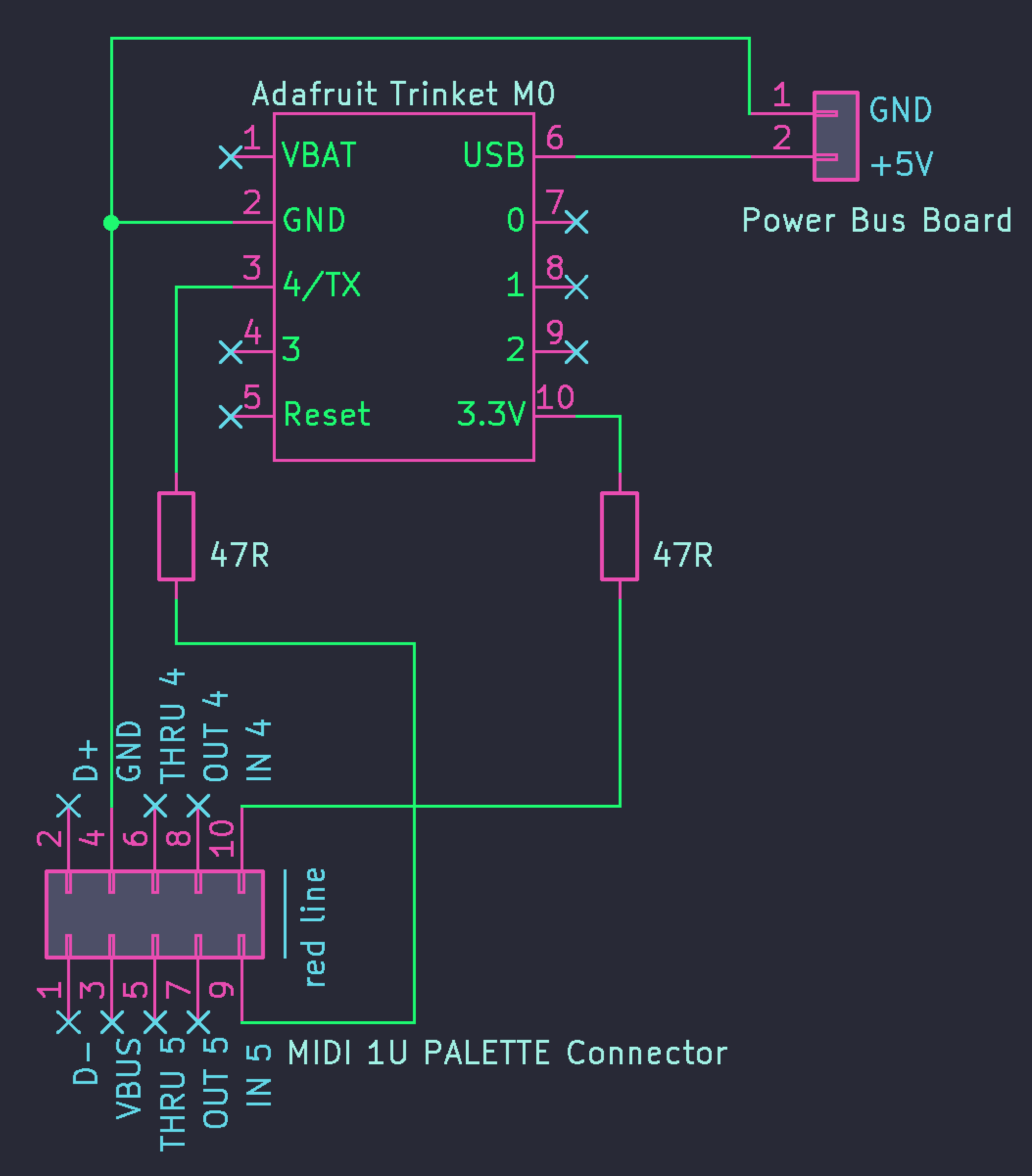
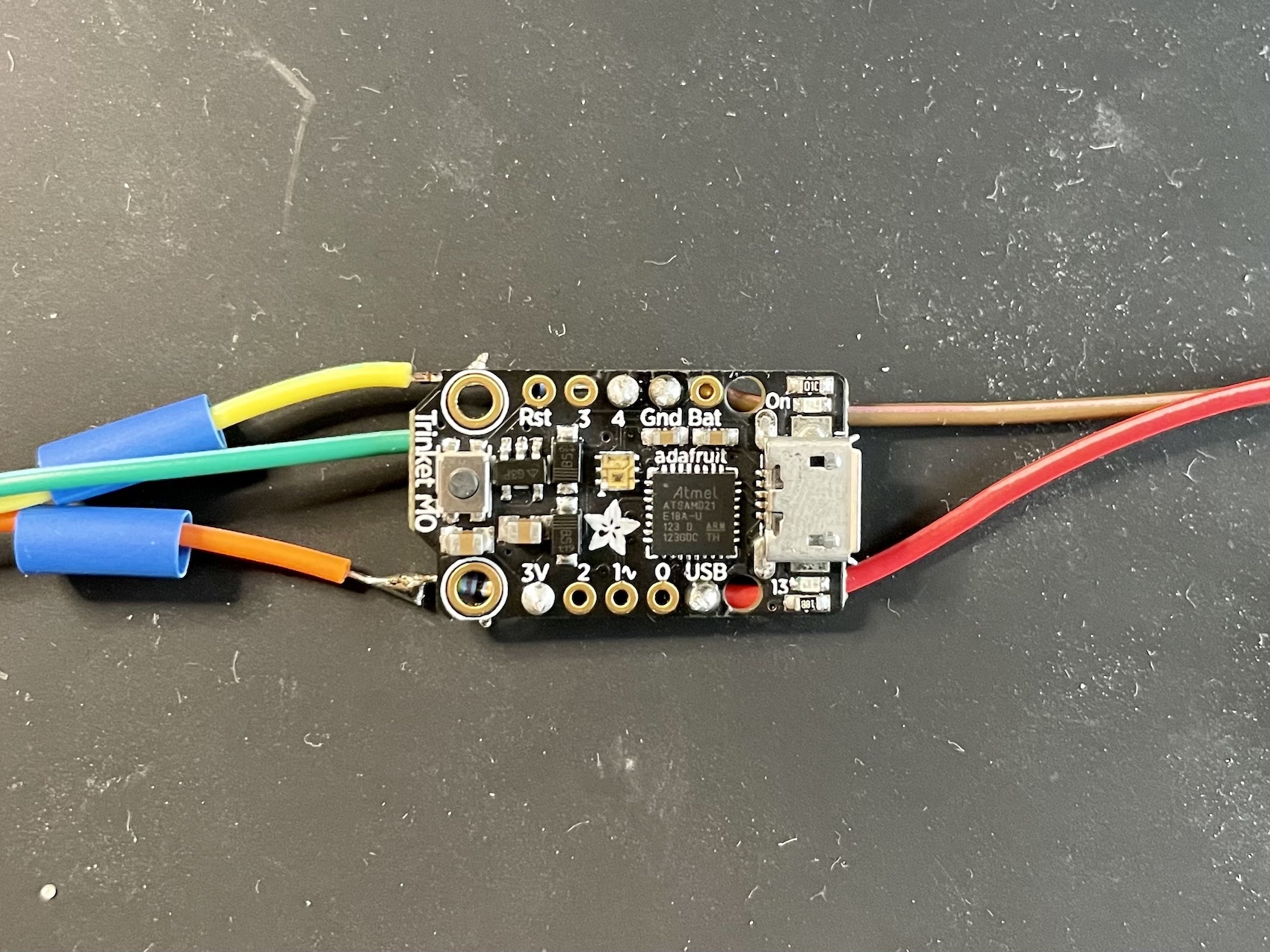
Because either a USB device (Metropolix) and a MIDI recipient (MIDI 1U) do not provide power, the Trinket needs external power. For that it is necessary to solder a cable to the pin named “USB” (don’t get confused, it means USB VBUS +5V) and two cables to the GND pin. One of the GND cables is needed later for MIDI out. The other two cables (one USB/+5V and one GND) will bee connected to your power source.
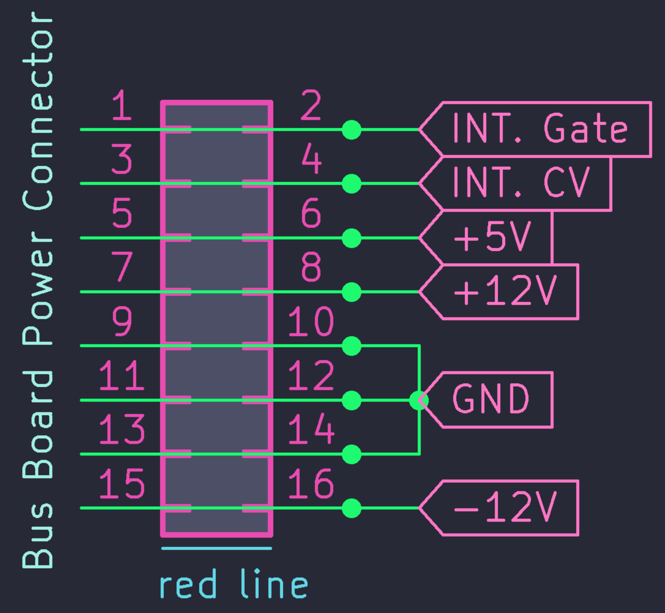
Most Eurorack bus boards have dedicated +5V connectors, but if not, it is also possible to use one of the standard bus board power connectors (see figure 2 - careful, don’t fry your Trinket …or whatever). The USB/+5V cable needs to be connected to a +5V pin and the GND cable to a GND pin. The easiest way to connect them are those little DuPont Connectors you find on the end of jumper wires.
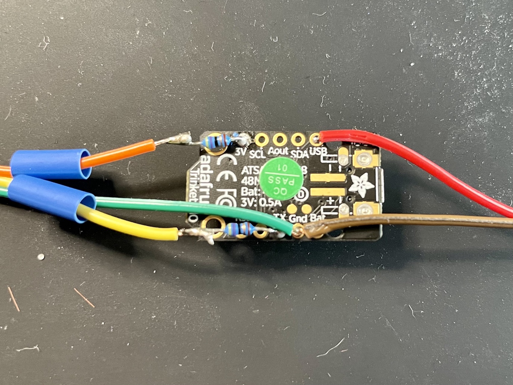
47 Ohm resistors need to be soldered either to the 4/TX pin and to the +3.3V output pin of the trinket. If you are using a microcontroller board with 5V outputs, use 220 Ohm resistors instead. Extend the resistors with cables. Those cables need to be connected to the MIDI 1U as shown in the schematic (figure 1).
The whole thing must be wrapped in shrinking tube or isolation tape or something to avoid shorts and damaging something!
Software
The Trinket is still pretty dumb (not really, but it can’t do what we want right now). So it has to learn it… with code. Luckily other people already wrote code for that so we can take a shortcut here.
I will not teach how to compile code and load it to microcontroller boards. Your trusted web search engine will help you with that.
This example code by Yuuichi Akagawa for a usb host library does exactly what we need. Thanks Yuuichi Akagawa!
(This will not work on every board! You might have to tweak it, search for other code - there is a lot - or write some lines yourself.)
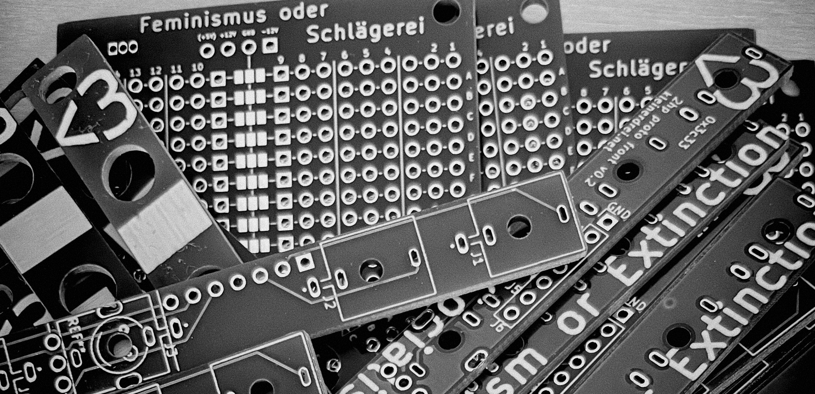
I like to build simple modules for my eurorack synthesizer myself. There is some stuff that is always the same. Mostly power related. Or the part where you need some sockets to plug your patch cables in. I’m just too lazy to start it every time from scratch again. So, after a bit of experimenting and building generic PCBs for the sockets part, I found out about the P-0+o prototyping board from Kristian Blåsol.
It is a really nice board to build little modules with. It has a dedicated place to put your power connector and three busses in the middle of the board for distribution.
I took this very good idea and designed a board fitting my personal needs. The P-0+o board seems to be more about real prototyping and tinkering around developing an idea. But I needed something to build a module I’d actually use. My “nucleus” board lacks of a few features of P-0+o, but adds some others.
I gave some of those boards to my friends. And because it can be a bit complicated, I promised to write some kind of a how-to – through whose introduction
you just made it. Congrats. Now to the interesting stuff.
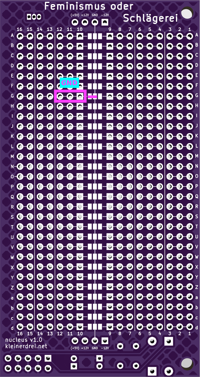
nucleus ist mostly used like a normal TriPad board. Components are placed on the board, connecting different horizontal sections of two or three holes. Interconnected holes and pads on the grid are indicated by a thin connecting line printed on the PCB. Breaks between sections are indicated by vertical lines between holes.
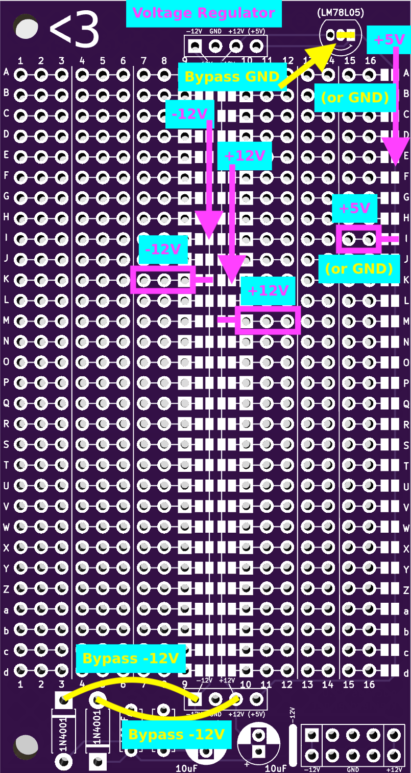
Power input
In the lower right corner is a spot to place a 2x5 pin header for standard eurorack power supply. To its left, it is possible to place capacitors and diodes. The diodes are meant to protect the module from reverse polarity, in case of a connector being plugged in the wrong way round. The capacitors are supposed to smoothen possible peaks to reduce noise.
For a quick draft, when this is not needed, it is possible to just bypass the “power cleanup” section with two pieces of wire from the lower holes of the 10μF capacitors to the connectors below the grid (see graphic “nucleus front”).
In the upper right corner a voltage regulator (my recommendation would be a LM78L05) can be placed to have +5V available for a microcontroller or something like this.
Power distribution
To distribute power over the board, there are four busses. On the front side we have two in the middle, the left one delivers -12V and the right one +12V. On the right edge of the board is a third bus. It delivers +5V from the voltage regulator. In the middle of the back of the board is only one bus for GND.
It is also possible to connect for instance the right two contacts where the voltage regulator should be placed (see graphic “nucleus front”) to get a GND bus instead of +5V.
To connect the adjacent section of holes to a bus join the two solder pads with a drop of solder (see graphics).
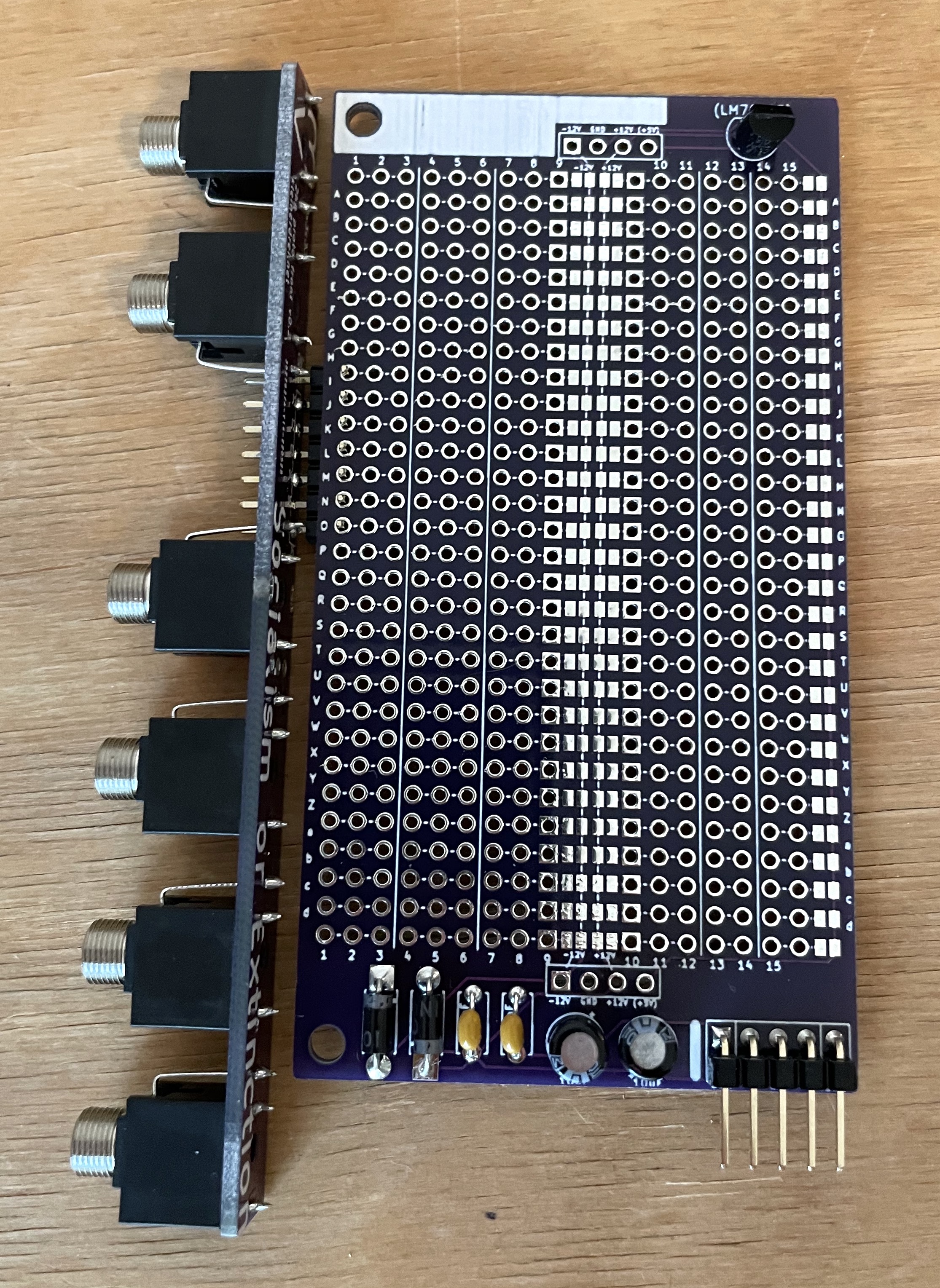
Yes correct, the board with the sockets is not soldered to the nucleus board. I just wanted to show how it could be used.
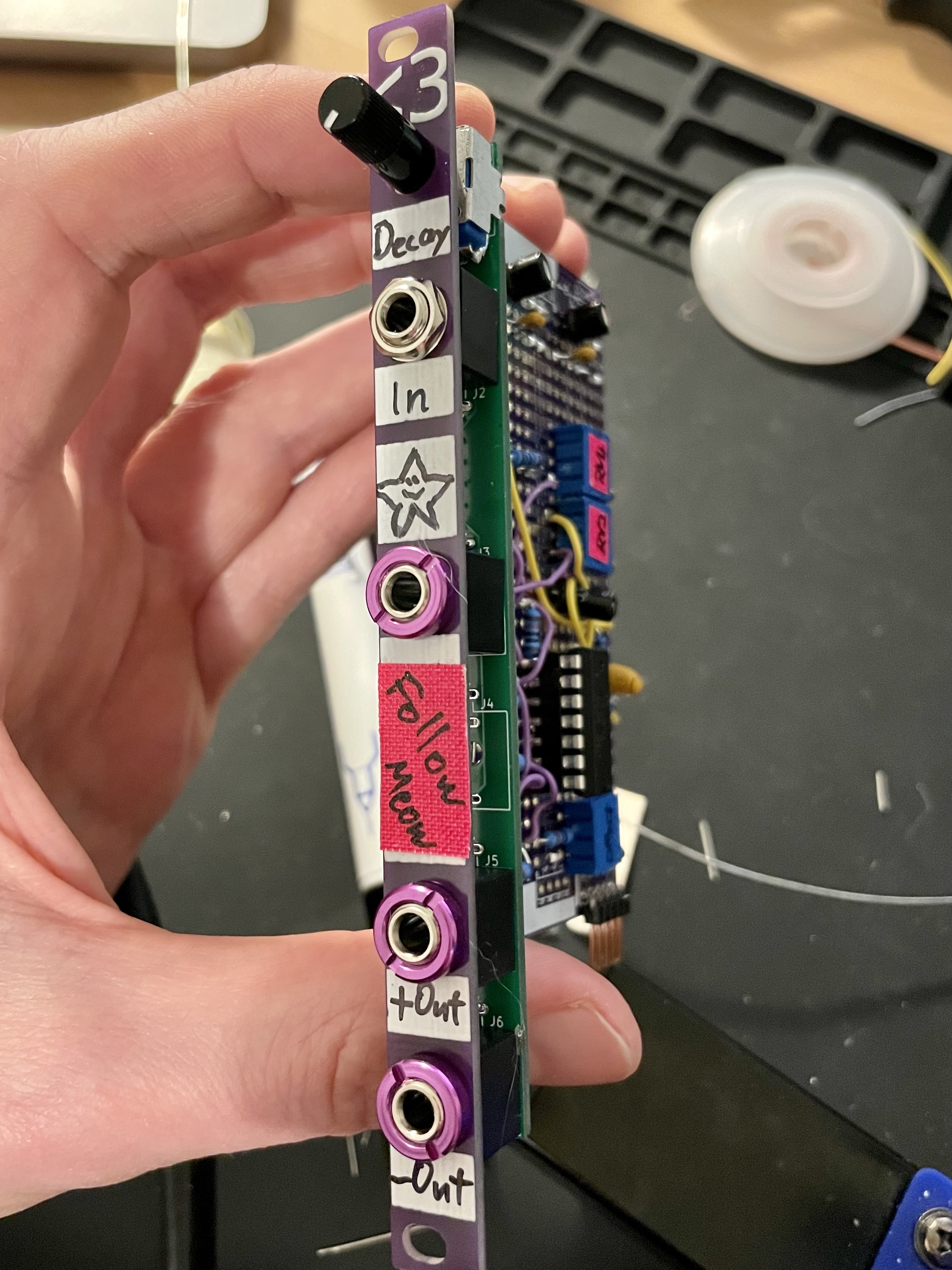
Follow Meow - an envelope follower, built using nucleus (older version)
Freund*innen von mir betreiben einen kleinen Laden für modulare Synthesizer (unbezahlte [aber] Werbung), hier in Köln. Und es kommt immer wieder vor, dass Personen in den Laden kommen, die interessiert sind, in das Thema einzusteigen und die Frage stellen, wie sie das am besten machen können. Die Frage ist wirklich schwer zu beantworten, weil modulare Synthesizer einfach so vielseitig sind und es total davon abhängt, was Du damit machen möchtest. Außerdem sind sie nicht ganz Preisgünstig, da ist es für die meisten nicht möglich mal eben voll zuzugreifen.
Wir haben jedenfalls darüber gesprochen, was man diesen Menschen wohl empfehlen könnte und das Thema hat mich danach nicht so recht losgelassen. Nach ein paar Tagen habe ich den Discord des Ladens mit meinen Gedanken vollgespamt. Um das ganze ein bisschen zu sortieren und vielleicht auch noch ein paar mehr Leuten bei diesen Überlegungen zu helfen, schreibe ich es nochmal hier auf.
Grundlegendes vorab
Üblicherweise haben Menschen, die sich für modulare Synthesizer interessieren, schon vorher Erfahrungen mit Elektronischen Instrumenten (im Computer oder zum anfassen) gesammelt. Ich halte diesen Text deshalb zwar einfach, erkläre aber nicht jedes Wort. Solltest Du Fragen haben, kannst Du mich gerne einfach kontaktieren.
Was ich hier vorschlage ist geeignet für Musik, die auf das Prinzip Wiederholung setzt. Das wäre zum Beispiel Techno-artige Musik im weitesten Sinne, funktioniert aber bestimmt auch für weitere Genres.
Looper
Ein Looper, also Geräte oder Software, die ein Stück Audio aufzwichnen und in Dauerschleife wiedergeben können (plus mehr natürlich), sorgt dafür, dass Du ansonsten nicht so wahnsinnig viel brauchst.
Die Idee ist, dass Du mit einem Looper nur eine einzige, einigermaßen vielseitige, Voice (Synthesizer-Stimme) benötigst und diese dann layern kannst. Erstmal eine Bass Line in einen Loop werfen, dann eine Lead Voice usw.… Du verstehst.
Es gibt einen ganzen Haufen an Geräten, die Dir das ermöglichen.
Vielleicht könnte das der Octatrack sein, der in der Ecke steht, weil er immer zu kompliziert war um was anderes damit zu machen
Oder es könnte ein Boss RC-505 sein. Geile Maschine! (Könnte mir vorstellen, dass man den MK1 günstiger gebraucht bekommt)
Eine Looper App wie Loopy Pro soll aber auch super gut funktionieren, habe ich mir sagen lassen und ist um einiges günstiger
Natürlich gibt es noch viel mehr, guck Dich ruhig mal um.
Features
Das Setup sollte ein paar Dinge auf jeden Fall können, damit Du richtig viel Spaß haben kannst.
Es sollte sein Tempo mit dem Looper synchronisieren können. Es braucht deshalb irgendeine Art von MIDI zu CV (Control Voltage == Steuerspannung; Damit wird in Modularen Synths alles mögliche gesteuert). Es gibt da auch noch andere Tricks, aber ich mache das jetzt mal ganz klassisch. Frag mich, wenn Du mehr wissen willst.
Es sollte irgendeine Form von Sequencing geben. Und zwar sowohl Trigger/Gate als auch Pitch/CV.
Dann die Voice selber. Hier empfehle ich für den Einstieg eine komplette Voice, also Klangerzeuger, Envelope, VCA und Filter im Paket. Zumindest habe ich für alle drei Setups jeweils eine ausgesucht.
Effekte. Was soll ich dazu schreiben. Bisschen Würze ist halt immer schön.
Output. Dein Looper kann erst mal nicht so viel mit dem ultra lauten Output Deines Euroracks anfangen. Deshalb muss das Signal auf Line Level runter gebracht werden. Falls Du noch ein solides analoges Mischpult, z.B. von Mackie rumligen hast, kannst Du es auch damit versuchen. Die kommen teilweise auch mit so lauten Signalen klar. Dann kannst Du Dir das Output-Modul erstmal sparen.
Hier kommt irgendwie keine Modulation vor, merkste, ne? Das schöne ist, dass Du in einen Looper total gut rein spielen kannst, während Du selber gerade am Knöpfchen drehst. Das wiederholt der dann ja immer schön für Dich.
Drums habe ich auch außen vor gelassen. Die können zum Beispiel aus Deinem Looper kommen. Alle drei Vorschläge oben können das mehr oder weniger gut. Möglicherweise hast Du ja sogar schon irgendeine Drum-Machine. Dann nutz die einfach. Mache ich übrigens auch so.
Falls Du aber auf jeden Fall Drums im Rack haben willst, empfehle ich Dir 1-2 Prok Drums, die sind super vielseitig und einfach zu bedienen. Oder aber den Tiptop Audio ONE Sample Player. Auch hier ist der Looper Dein bester Freund.
Außerdem benötigst Du natürlich irgendeine Art von Gehäuse und eine Stromversorgung. Auf beides gehe ich hier nicht näher ein. Nur so viel: Ein Gehäuse kannst Du Dir im Zweifel für Den Anfang aus etwas Pappkarton und Klebeband bauen. Und so lange Du noch nicht super viele Module hast, kommst Du mit einem simplen Power Supply Modul wie z.B. dem μZeus von Tiptop Audio ganz schön weit. Weil viele Leute die für den Anfang nutzen, gibt es die oft günstig irgendwo gebraucht.
Zu günstig fällt mir noch ein, dass Du mit DIY Kits oft noch ganz gut Geld sparen kannst. Allerdings musst Du dann natürlich bereit sein, einen Lötkolben zu schwingen.
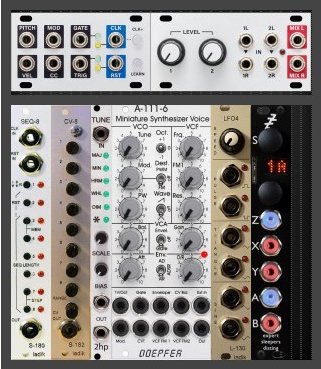
Fangen wir super simpel und ganz klein an. Hier bin ich mal von einem Intellijel Case mit 1U-Reihe ausgegangen, das MIDI und Audio-Anschlüsse hat. In erster Linie, der Vollständigkeit halber.
Die Synchronisation mit dem Looper findet über ein Intellijel MIDI 1U statt.
Das lässt sich auch fürs Sequencing nutzen, wenn Du Dir die Module dafür erstmal sparen möchtest. Dann brauchst Du nur ein Gerät, dass das für Dich übernehmen kann. Kann auch Dein Laptop sein.
Ansonsten schlage ich für das Sequencing aber mal den Ladik S-180 vor. Ein super simpler 8-Step-Sequencer, der aber durchaus noch ein bisschen mehr kann, als man zunächst denkt.
Den erweitere ich dann noch um den Expander Ladik S-182. Damit bekommt er gleich noch die Möglichkeit Pitch/CV zu sequencen und nicht nur Trigger.
Ladik Module sind ähnlich wie die von Doepfer recht günstig und eigentlich ziemlich gut. Dafür nicht besonders aufregend im Design, aber mir gefällt das ehrlich gesagt.
Falls Du auch noch Drums sequencen willst, kannst Du noch über das Ladik S-181 nachdenken. Tatsächlich kannst Du von diesen Erweiterungen mehrere hintereinander hängen und richtig tolle Sachen machen.
Ich würde Dir noch einen einfachen Pitch Quantizer, wie z.B. den 2hp Tune empfehlen. Ist nicht unbedingt nötig, macht aber vieles einfacher, wenn Du Wert darauf legst, dass Deine Musik sich an Tonleitern hält.
Die eigentliche Voice ist die Doepfer A-111-6 Miniature Synth Voice. Eine Super vielseitige und ganz fantastische komplette Stimme. Sie ist analog und kannt dicke Bässe und tolle Lead Sounds. Ich habe noch den LFO Ladik L-130 spendiert, weil die Bässe mit ein bisschen PWM (Pulsweitenmodulation) noch besser werden. Kannst Du aber auch erstmal drauf verzichten.
Für Effekte nutze ich hier das Expert Sleepers Disting mk4.
Das kann ungefähr eine Millionen Sachen. Unter Anderem eben Effekte. Ich verspreche Dir aber, dass Du Dich in der Zukunft, bei Deinen modularen Forschungen, noch oft über dieses Modul freuen wirst.
Dieses Setup ist am meisten nach meinem Geschmack und es beinhaltet tatsächlich auch eine ganze Menge Module, die ich in meinem eigenen Rack derzeit benutze (Gut, das gilt auch für den letzten Vorschlag, aber hier sind es mehr). Mit diesem Rack bist Du weniger damit beschäftigt, Melodien, Rhythmen usw. zu “programmieren”. Du generierst sie viel mehr. Die Kreativität fließt hier eher in die Grenzen, die Du dem Zufall setzen möchtest und welche Patterns, Töne und so, Du auswählst oder verwirfst. Es ist sehr “perfomable”, finde ich. Du hast aber auch nie die 100%ige Kontrolle.
Dieses Setup beinhaltet außerdem ein paar Module, die Du als DIY Kit bekommen kannst. Außerdem kannst Du das in so gut wie jedes herkömmlich Case bauen. Keine 1U Reihe oder spezielle Intellijel-Anschlüsse, oder so.
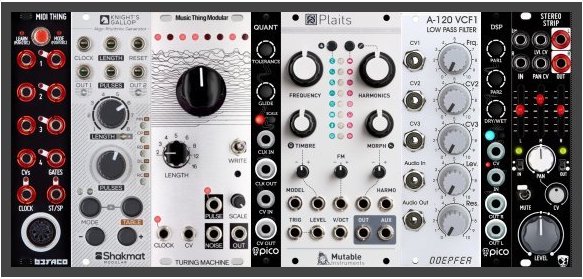
Die Synchronisation mit dem Looper erledigt ein Befaco MIDI Thing. Das Teil kann wirklich viel und ist ein bisschen mit Kanonen auf Spatzen geschossen. Sieh es mal als Investition in die Zukunft. Du könntest Dir auch hier die Sequencing Abteilung sparen, wenn Du irgendeine Art von MIDI-Sequencer verwendest. Gerade bei diesem Setup wäre das aber ein bisschen schade, finde ich. Es ist ja gerade schön, hier mit dem Kontrollverlust zu spielen.
Das Sequencing besteht hier aus zwei bis drei Modulen.
Trigger kommen aus dem Shakmat Modular Knight’s Gallop, einem super coolen Rhythmusgenerator. Ich liebe das Ding. Es ist sehr vielseitig und kann unter anderem auf seinen zwei Kanälen Rhythmen ausgeben, die sich auf einander beziehen, was ich sehr mag.
Die Pitch-Informationen kommen aus meinem absoluten Lieblings-Modul, der Music Thing Modular Turing Machine. Um es viel zu kurz zu umreißen: Ein loopable Random Pitch/CV und Trigger Generator.
Du könntest mit der Turing Machine prinzipiell sogar auch den Knight’s Gallop ersetzen, ich finde es so aber besser. Guck Dir aber auf jeden fall auch die vielen vielen Expander für die Turing Machine an. Das Modul ist auch wahnsinnig gut als Modulationsquelle geeignet. Probier das auf jeden Fall aus. So werden Deine Loops abwechslungsreicher!
Zuletzt haben wir wieder einen Pitch Quantizer, den Pico Quant von Erica Synths. Der ist auch hier nicht unbedingt nötig (kommt ein bisschen drauf an, was für Musik Du machen willst).
Zur Klangerzeugung schlage ich Plaits von Mutable Instruments vor. Das ist wohl die vielseitigste komplette Voice, die ich kenne. Das kann wirklich fast alles. Abgesehen davon ist es Open Source. Das bedeutet in diesem Fall, dass Du
a) aus einer riesigen Auswahl von Clones auswählen kannst, je nachdem was Dein Geldbeutel und Dein Geschmack Dir so sagt und
b) auf teilweise ganz großartige alternative Firmwares umsteigen kannst.
Vielseitig, ich sach Dir…
Ebenfalls nicht unbedingt nötig ist der Doepfer A-120. Ich finde aber, dass Plaits durch einen guten Filter noch mal richtig was gewinnt. Und das ist meiner Meinung nach einer der besten Filter, die man in der Preisklasse (günstig) bekommen kann.
Effekte kommen aus dem Pico DSP von Erica Synths. Acht verschiedene, teilweise richtig gut klingende Effekte. Der große Spaß bei dem Modul ist aber eigentlich, dass Du, wenn Du irgendwann mal mehr willst, es mit einem XODES BCI modifizieren (lassen) kannst. So kannst Du die Effect-Cards des Tiptop Audio Z-DSP benutzen. Einfach super gut!
Und am Schluss kommt der Sound mit Hilfe des DivKid Stereo Strip aus Deinem Modularsystem raus und rein in den Looper. Das Modul habe ich selbst leider noch nie benutzt, finde es aber ziemlich spannend. Es kann Eurorack und Line Level In & Out, Stereo EQ, VCA, Panner, Distortion und hat außerdem noch einen Mute-Schalter. BÄM!
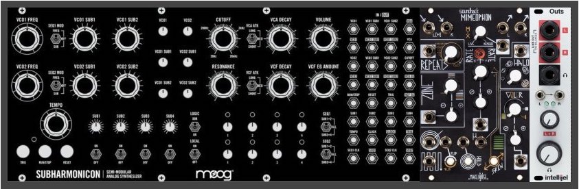
Der dritte Vorschlag besteht aus nur drei “Modulen”, ist aber trotzdem preislich nicht ganz unten angesiedelt, auch wenn ich behaupten würde, dass Du viel für Dein Geld bekommst. Außerdem noch eine Anmerkung: Ich besitze selbst kein Modul aus dem Setup, finde sie aber ziemlich cool.
Ob das jetzt wirklich meine Empfehlung ist, wenn Du komplett neu einsteigst, weiß ich gar nicht so recht. Modular ist halt schön, weil es modular ist und hier wird schon sehr viel zusammengepackt. Falls Du aber bereits einen Moog Mother Synth als Einzelgerät haben solltest, könnte das ein guter nächster Schritt sein.
Mit den semi-modularen Mother Synthesizern von Moog hast Du eigentlich schon alles, was Du brauchst. MIDI zum Sync mit Deinem Looper, Sequencer und Voice. Ich habe mal die(?) Subharmonicon genommen, weil ich sie am interessantesten für mich persönlich finde. DEFAM und Mother-32 sind aber auch ganz toll.
Für die Effekte schlage ich Mimeophon von Make Noise vor. Ich schleiche schon lange um dieses Modul herum und finde es ganz fantastisch. Es ist aber auch ganz schön teuer und eigentlich habe ich ja auch schon tolle… na ja, Du weißt schon. Es fällt mir schwer, das Ding zu beschreiben. Es einfach als ausgebufftes Delay mit sowas wie Reverb zu bezeichnen, wäre zu kurz gegriffen. Guck Dir vielleicht einfach mal ein paar Videos bei Youtube an.
Um die Sounds in Deinen Looper zu bekommen habe ich mich für Intellijel Outs entschieden. Das ist einfach ein ziemlich solides Output-Modul. Aber ganz ehrlich, komplett ersetzbar durch ein anderes. Und es würde mich nicht wundern, wenn Du es mit klugem Patching auch einfach weglassen könntest. Dafür kenne ich mich aber zu wenig mit den Moog Mothers aus.
Zum Schluss
Was für ein Ritt.
Vielleicht noch abschließend ein paar Worte zu den Vorschlägen: Wie ich schon schrieb, das schöne an modularen Systemen ist, dass sie modular sind. Dir gefällt der erste Vorschlag, aber Du willst für deine Effekte dieses geile Mimeophon? Mach halt. Das ist sicher super cool.
Das gilt an ganz vielen stellen. Du kannst Dinge kombinieren, wie es Dir Spaß macht. Ich habe die drei Setups so zusammengestellt, wie es mir gerade in dem Moment schlau vorkam, aber am Ende bist Du vollkommen frei. Teilweise habe ich auch nur verschiedene Module für den gleichen Zweck ausgepackt, um zu zeigen, dass es unterschiedliche Geschmacksrichtungen gibt.
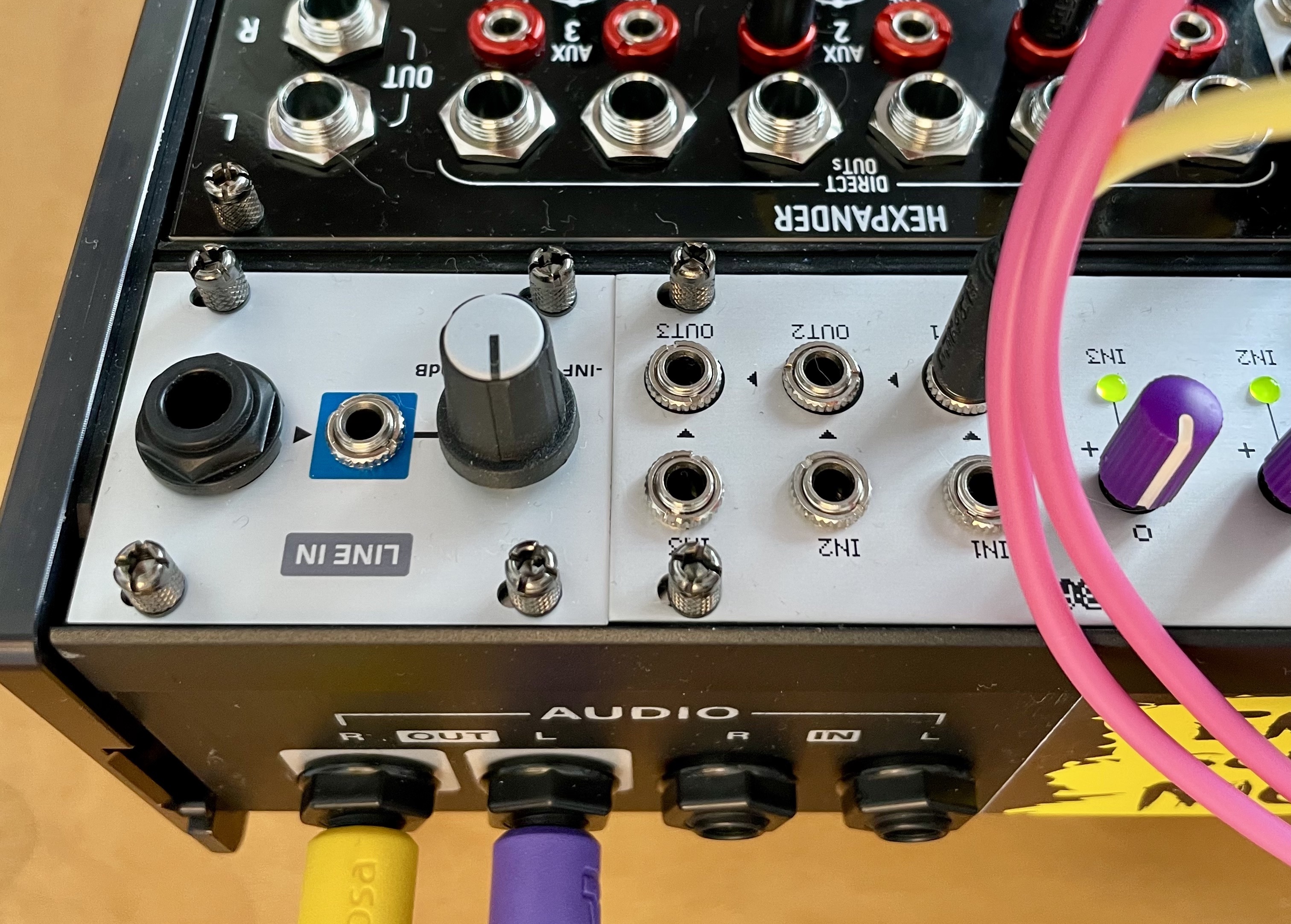
I got a new case for my Eurorack synthesiser. One of those fancy Intellijel Performance ones, with audio In and Out jacks on the rear panel. I like the idea of having at least those cables out of my way very much. Of course, like maybe every Non-Intellijel mixer, my Befaco HEXMIX has no connector for this. But blessed are they who do have a soldering iron and are not afraid to use it on their precious gear.
It is not very difficult to make your own connection cable and attach it to your mixer. I will describe in this text how I did it with my HEXMIX respectively HEXPANDER, but this should be possible with most other Eurorack mixers. Keep in mind that Eurorack audio is very loud (around 5-10Vp) compared to line level audio. The output Jacks of your case will not magically convert your loud Eurorack signal into a moderate line level signal. You could fry your connected gear!
What you need:
a multimeter and an audio cable to plug in the jacks you want to measure (only if you have different gear then I’m using here)
a soldering iron and some solder
a 6-pole plug - one of those you use for Eurorack power supply but only 6-pole. Those plugs are called “Pfostenbuchse” in German. Funny word…
a 6-pole ribbon cable. I just ripped away 4 wires of a 10-pole ribbon cable.
One more thing: The HEXPANDER’s Master Out and the Audio Jacks on the rear of the Intellijel cases are balanced. What I’m explaining here breaks this. You will get an unbalanced signal out of your case’s jacks. It would be possible to do this balanced, but I was lazy and I don’t need it (at the moment). If you need it balanced, because you have to use long cables, you can still use the HEXPANDER’s Master Out. Maybe I will update this How To in the future.
Okay, let’s do this
On the HEXMIX you have two ways to go. The first would be to use the Master out of the HEXMIX module. If you want to use those, configure the switches “S200” on the back of your HEXMIX to line level (remember, don’t fry you gear!).
The other way would be to use the Master Out of the HEXPANDER module which already is line level. I chose the latter.
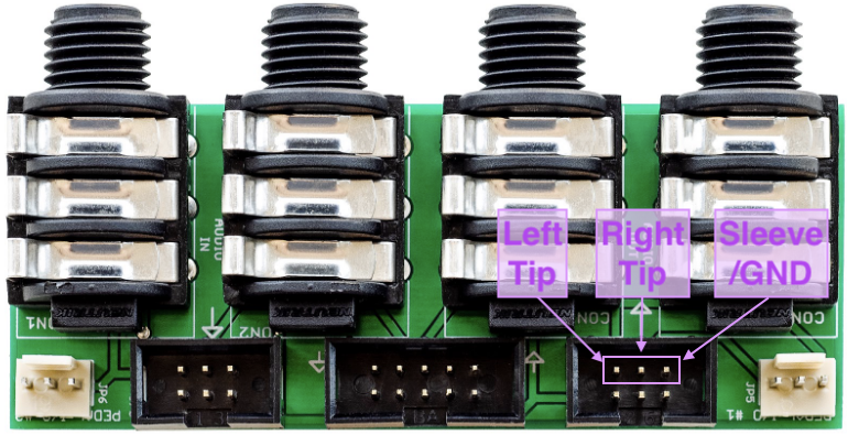
On the other side we have Intellijel’s Audio Jacks Board. In my case the 2nd generation (take a look to determine). The output signals go through the right 6-pin plug (“Pfostenstecker” in German). The easiest way to measure which pin is for what is by plugging in a cable in one of the audio jacks and measure with a multimeter from tip and sleeve of the cable to the different pins. Then do it again for the other jack (yep guessing would also be easy at this point, smart ass).
You don’t have to do it, if you have a 2nd generation Audio Jacks Board. I already did it for you.
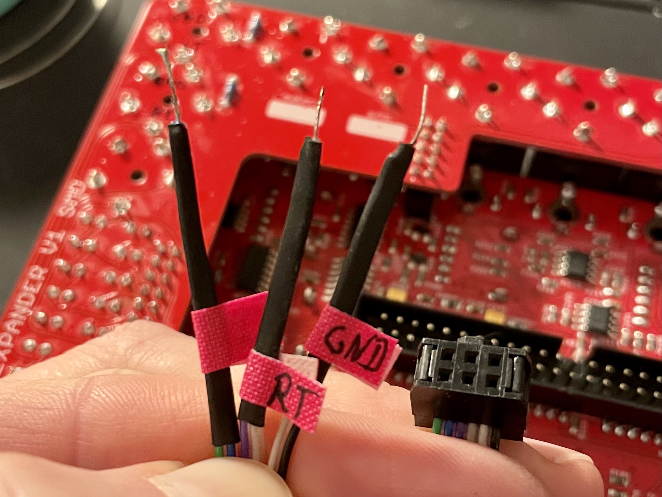
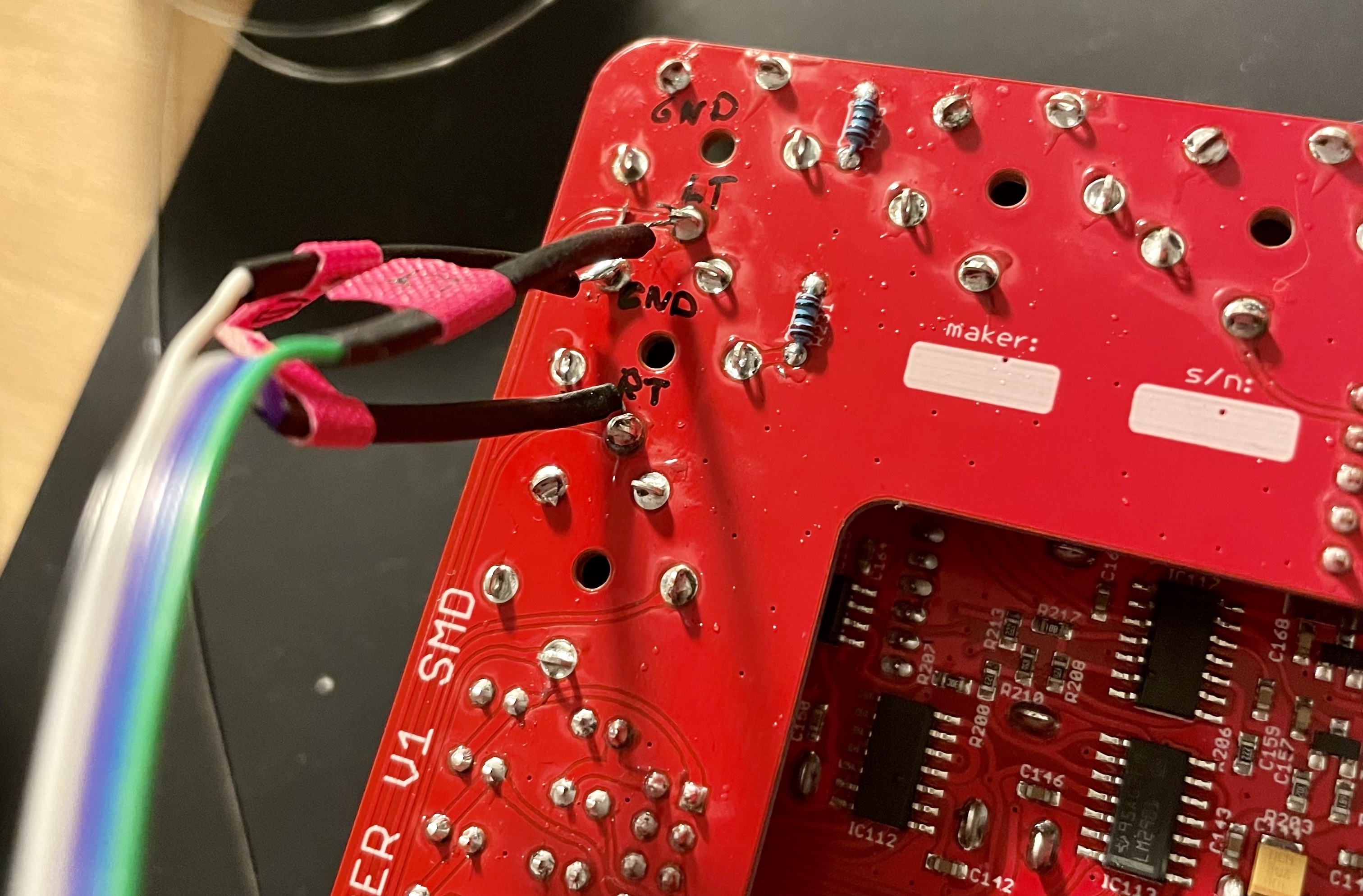
Put the Pfostenbuchse (plug) on one end of the cable. Split the other end of the cable and cut away the unused wires. Holding the wire like I do on the photo, the right wire of any pair is used (blue, grey, black). If you want to make sure, use your multimeter.
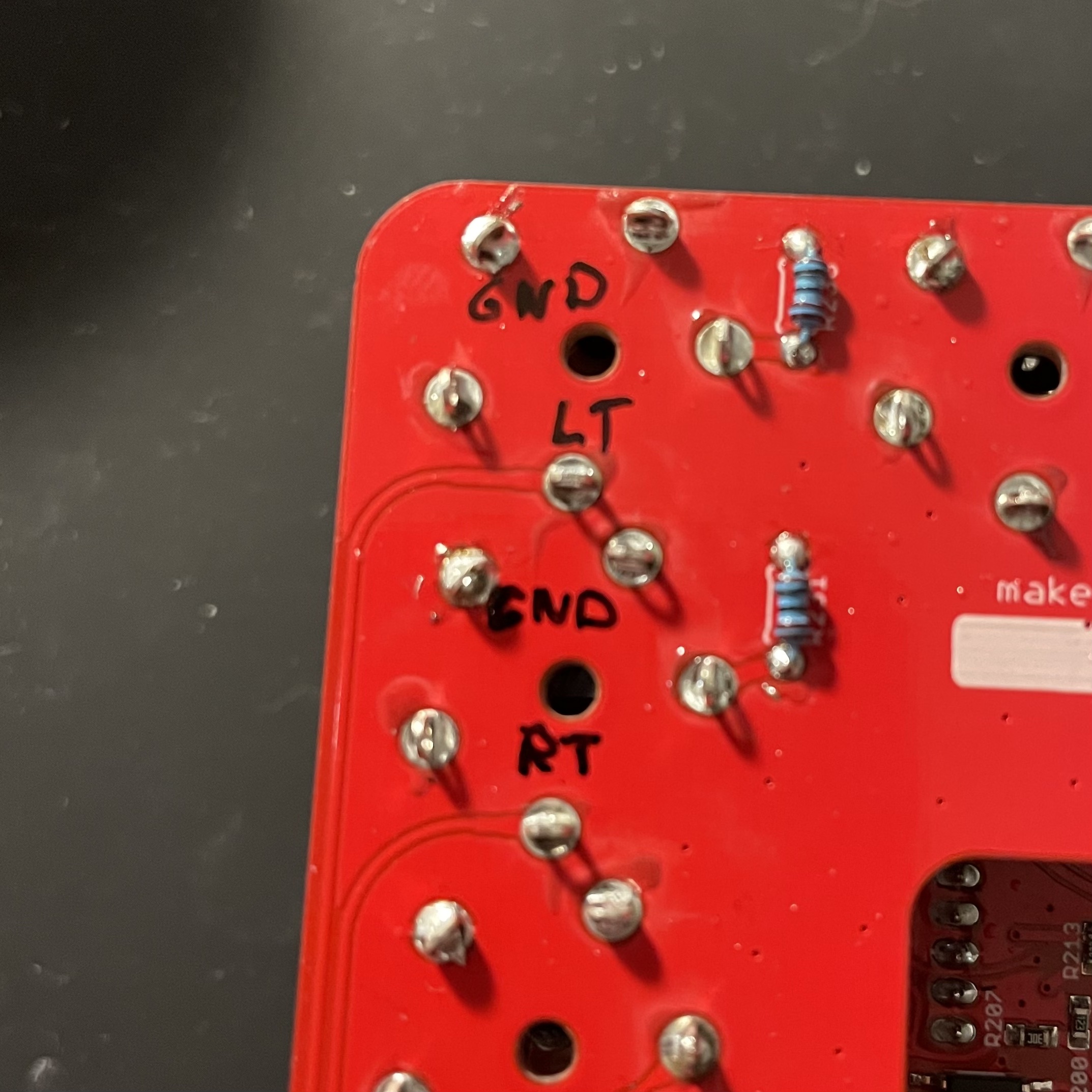
On your mixer, finde the pins of the output jacks and determine which one is for what. If you are also using a Befaco HEXPANDER and it looks like mine (there are variations) you can use my accurate and good looking markings (GND = ground/sleeve, LT = left tip, RT = right tip).
If it looks different or you are not using a HEXPANDER, measure like described above. Plug a cable in the jacks. Measure from tip and sleeve to the pins until you know. The sleeves are ground. All ground is connected. This is why there is only one ground wire for the sleeve pins of the left and the right jack in our ribbon cable.
Solder the separated wires of the ribbon cable to the identified pins and plug the other end of the cable into the Pfostenstecker (plug) of the Audio Jacks Board in your case.
If you managed to not break your stuff (Which would absolute be not my fault!), you might be happy now. I was. I still am.
Have fun and maybe show me a picture or something audible of your work. I would appreciate it very much. You can reach out to me via social media.
Getting chords out of a modular synthesizer is not fun. At least not for me. Maybe it is for people with more skill or bigger systems or a stronger masochistic streak in them than I got. But for me, it’s close to impossible.
I have a Plaits which can do chords, but I like and use it for other reasons.
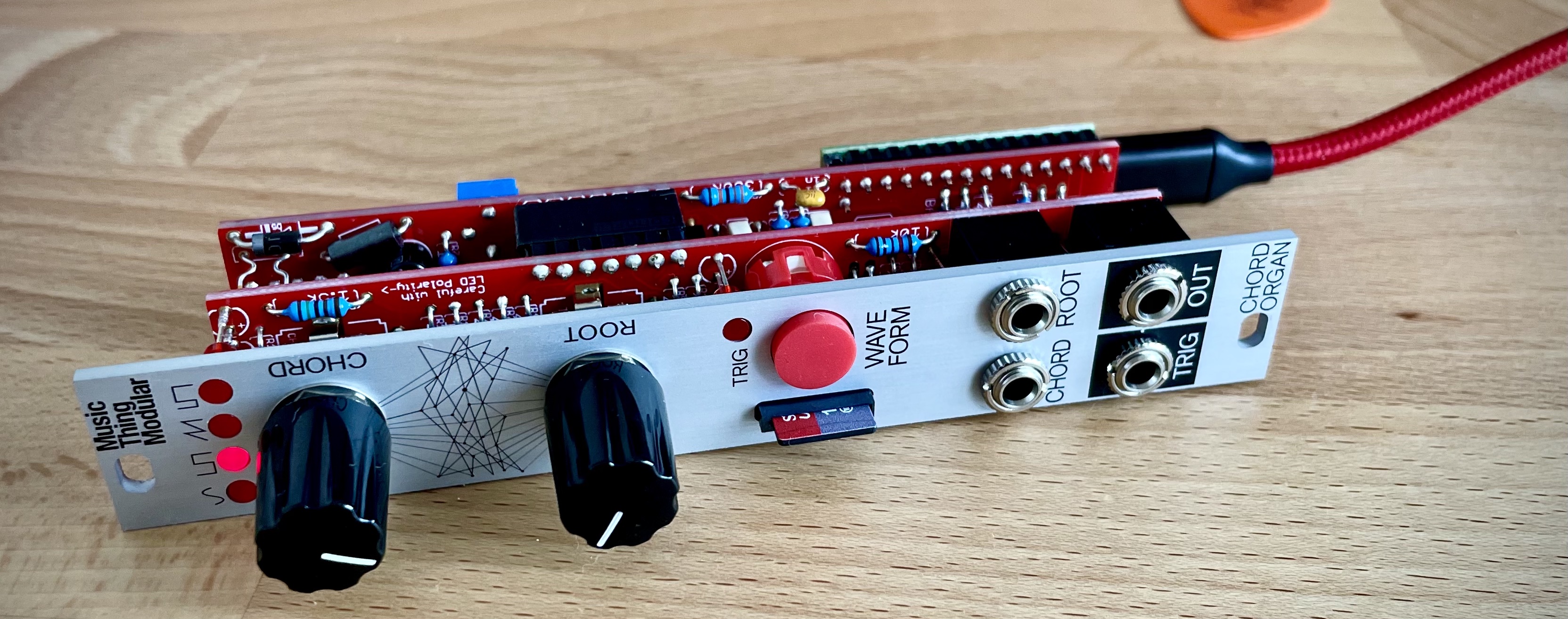
What I really like and what gives me a warm feeling is the sound of (maybe a bit jazzy) chords consisting of a bunch of simple sign waves. Not a difficult thing to do on your favorite polysynth, but as I said, not fun on a modular. And when I saw the Chord Organ by Music Thing Modular do it in the easiest way ever, I wanted one.
About the Chord Organ?
The Chord Organ is an alternative firmware of another eurorack module by Music Thing Modular respectively Tom Whitwell, the Radio Music, kind of a sampling radio thingy. The heart of the module is a teensy microcontroller which can be freely programmed. So, the module can be seen as a more or less simple platform for all kinds of possible eurorack modules.
The Chord Organ plays chords. The root note of the chord is defined by a CV input and a knob. The same counts for the chord shapes. Up to 16 shapes can be defined in a configuration file (CHORDORG.TXT) and be selected via another CV input and knob. In addition, it is possible to configure some more features in this file, like glide, note stacking and some more. Fot the fans of microtonal music it is also possible to create a separate tunig file (TUNING.SCL), to have the Chord Organ tuned in an alternative way.
That is roughly it.
Show me what a CHORDORG.TXT looks like!
This is what a CHORDORG.TXT looks like!
…could…
!RANGE 39
!WAVES
!STACK
!GLIDE 80

1  [0,4,7,12,0] Major
2  [0,3,7,12,0] Minor
3  [0,4,7,11,0] Major 7th
4  [0,3,7,10,0] Minor 7th
5  [0,4,7,11,14] Major 9th
6  [0,3,7,10,14] Minor 9th
7  [0,5,7,12,0] Suspended 4th
8  [0,7,12,0,7] Power 5th
9  [0,5,12,0,5] Power 4th
10 [0,4,7,8,0] Major 6th
11 [0,3,7,8,0] Minor 6th
12 [0,3,6,0,3] Diminished
13 [0,4,8,0,4] Augmented
14 [0,0,0,0,0] Root
15 [-12,-12,0,0,0] Sub Octave
16 [-12,0,0,12,24] 2 up 1 down octaves
The modifications: Chord Organ Chamäleon
So, I got my kit from the UK (Did I ever mention what a pain in the ass this brexit clusterfuck is? I will never get over it…), built it and played around with it. It is great. I love it! <3
What seemed a bit unnecessary to me was whenever I wanted a different behavior of the module, I had to remove the SD card, go to my computer, make changes to the config file and then go back to my modular to re-insert the SD card and reload. So, I wanted to change this (and maybe because the feature creep is strong in me).
With my modified version of the Chord Organ firmware it is possible to have up to ten different config files on the SD card. They would be called: CHORDORG.TXT, CHORDORG1.TXT, CHORDORG2.TXT…CHORDORG9.TXT
Loading the next file is done by a long butten press (at least for one second). The number of blinks of the waveform LEDs indicate which file will be loaded.
The long button press was formerly reserved to toggle the stacked notes feature on and off. But since note-stacking is also configurable in the config file, this feature still exists, if wanted.
I also made the alternative tuning file configurable by using !TUNING <FILENAME>. A config file with an alternative tuning could look like this:
!WAVES
!STACK
!TUNING 08-EDO.scl

1  [0,4,7,12,0] Major
2  [0,3,7,12,0] Minor
…
This way, it is possible to cycle through different tunings, if you want to.
I for my part have no clue about alternative tunings, so sorry for the bleeding ears in my little demo.